For some reason, I have kept around a remote control of a garage door we had 20 years ago, made by American-Door, where its LED was still blinking after all this time!
Since I have started playing with SDR for a while now, I decided to give this remote control one last use, by figuring out what made that old garage door operate. As usual, there was no information on it that could indicate either the frequency or the modulation being used. I started scanning the spectrum using my cheap RLT-SDR (and SDR#) for known frequencies, like 315MHz, 433MHz, and 868MHz while pressing the remote control buttons. No luck at all. So, I cracked it open to see what the circuit could tell me.
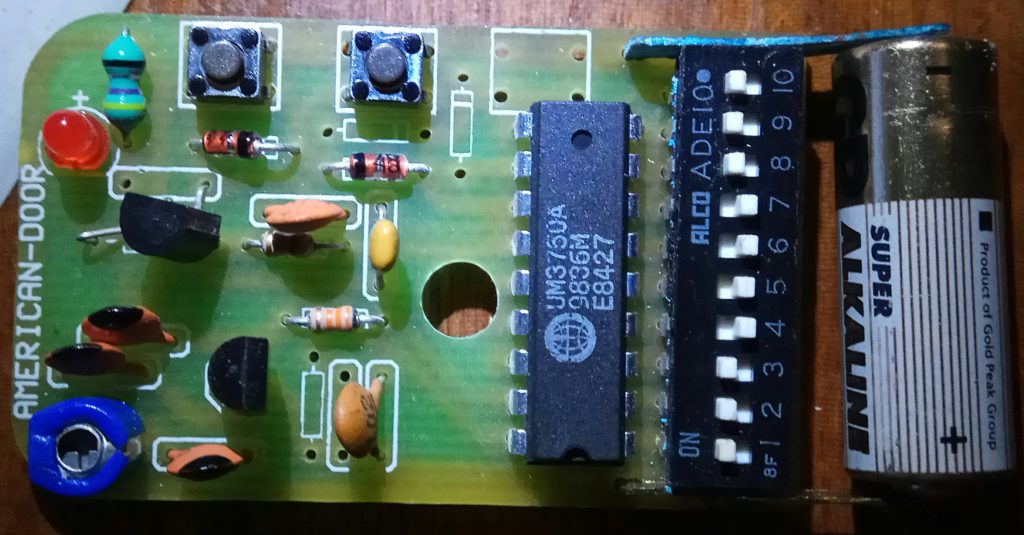
No sign of a crystal oscillator, which is usually present in such remotes. So, there has to be a tuned LC circuit that does the oscillation instead. OK, the capacitors are quite distinguishable, as well as the variable one (the blue one on the top left of the remote). But where is the inductor?
Having no clue on how to proceed, I asked around at the AskElectronics subreddit and some guys there were actually very helpful.
It turns out that the inductor is that bulky resistor-like component at the top-right corner of the remote, which gives us 470nF ±20% given its color code.
Another guy, at the same subreddit, mentioned that the variable capacitor (blue trimmer) could be between 2-5pF, or an average of 3.5pF.
From my early years as an electronics engineer, I still remember that one can calculate the resonant frequency of an LC circuit from the equation 1/(2*pi*sqrt(L*C)), which, for the above values, gives us ~126.4MHz.
Once more, I fired up SDR# and tuned it at about 126MHz. And there was success! The remote was indeed transmitting at that frequency, but was totally unstable. The signal was jumping around frequencies like crazy. Seems that some components have been worn out over the years which mess up the tuning.
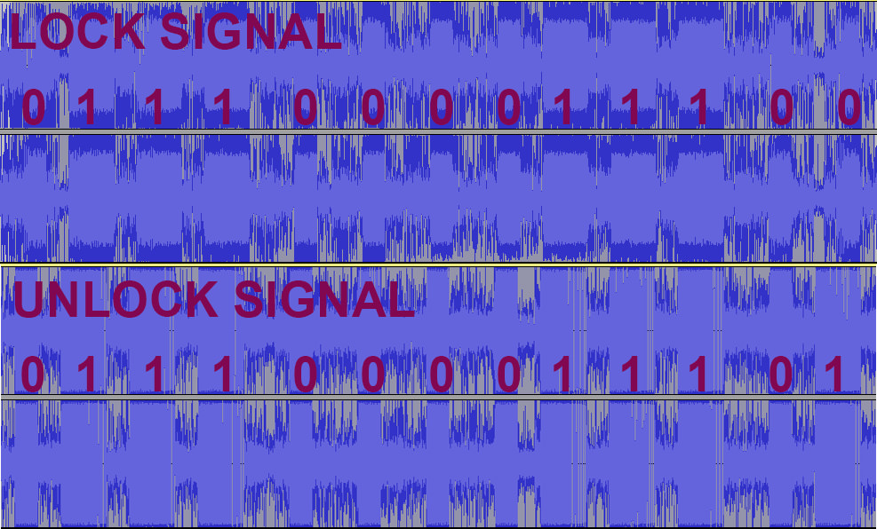
I went ahead and recorded the transmitted signals in SDR# in order to try and analyze them in Audacity. I found out that the modulation was, as expected, ASK or OOK and that the sent signal codes are comprised of a single digit preamble (0), then the setting of the dip switches (1110000111) and two more digits in the end. It seems that the only difference in the lock/unlock code is the last digit. Here is an attempt to visualize my thoughts/findings: