Many months now I wanted to test the logic analyzer feature of the bus pirate, which is documented here.
In order to do so, I created a simple circuit with couple of components I had lying around. Specifically, I decided to make a square wave frequency generator using a HCF4060BE binary counter, so that the output of the logic analyzer would be quite clear. The circuit is the following:
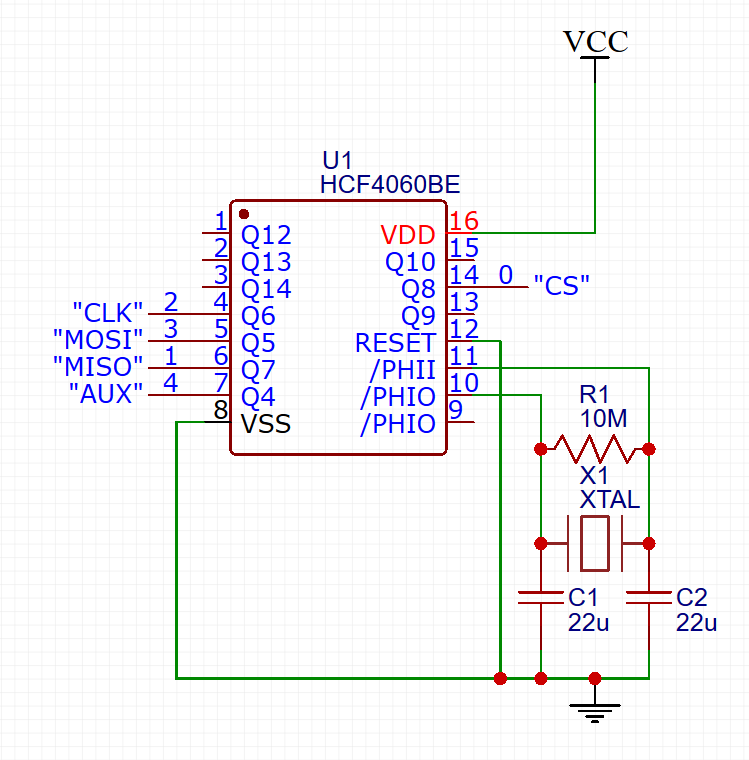
And here is the messy breadboard version:
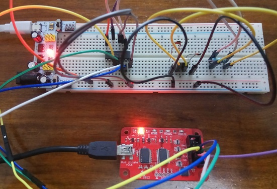
Connections between the bus pirate and the 4060:
| Probe channel | Bus pirate pin | HCF4060 pin | Frequency |
|---|---|---|---|
| chan0 | CS | Q8 (pin 14) | 74.583KHz |
| chan1 | MISO | Q7 (pin 6) | 148.655KHz |
| chan2 | CLK | Q6 (pin 4) | 297.311KHz |
| chan3 | MOSI | Q5 (pin 5) | 594.185KHz |
| chan4 | AUX | Q4 (pin 7) | 1.188MHz |
Make sure that your Bus Pirate firmware is v3.0 or later. With the bus pirate you can have up to 5 channels. Yeah, I used ’em all in this example.
I used a 4MHz crystal in the above circuit, thus the “weird” frequencies you see in the table. With a 2.4576 MHz one, you will get more common baudrates.
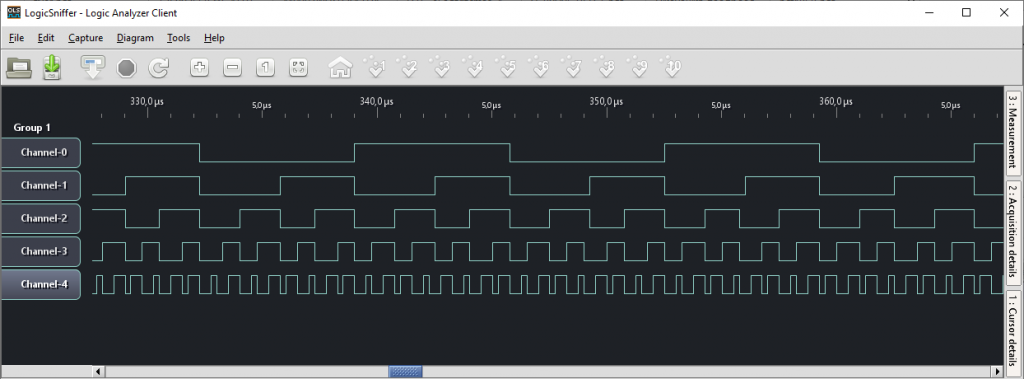
After you set up the connections and power up, launch the Open Bench LogicSniffer software and press “Capture” to start capturing samples from your bus pirate.
Logic analyzer output:
Channel information using the “Measurement mode” (under Tools menu):
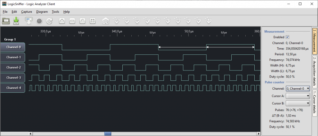
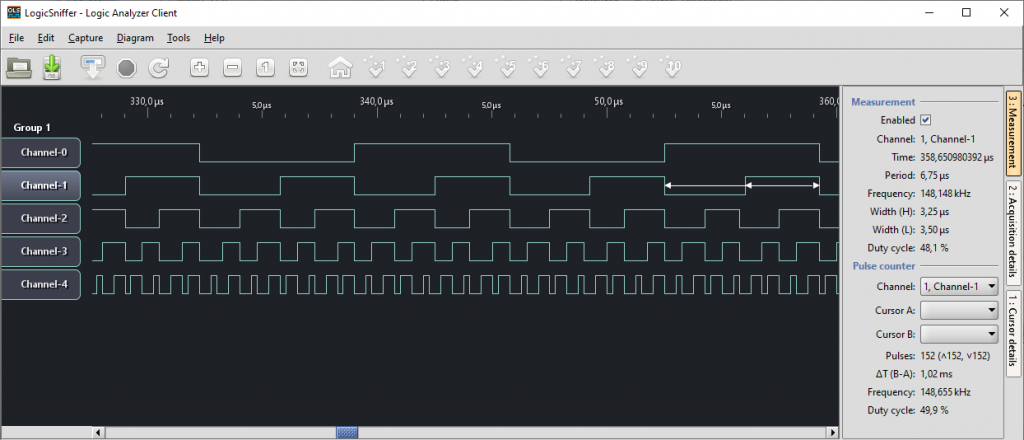
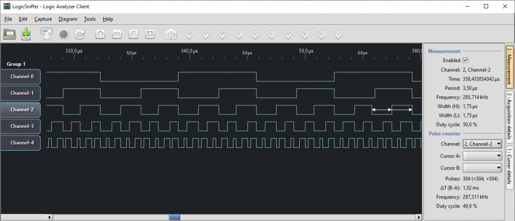

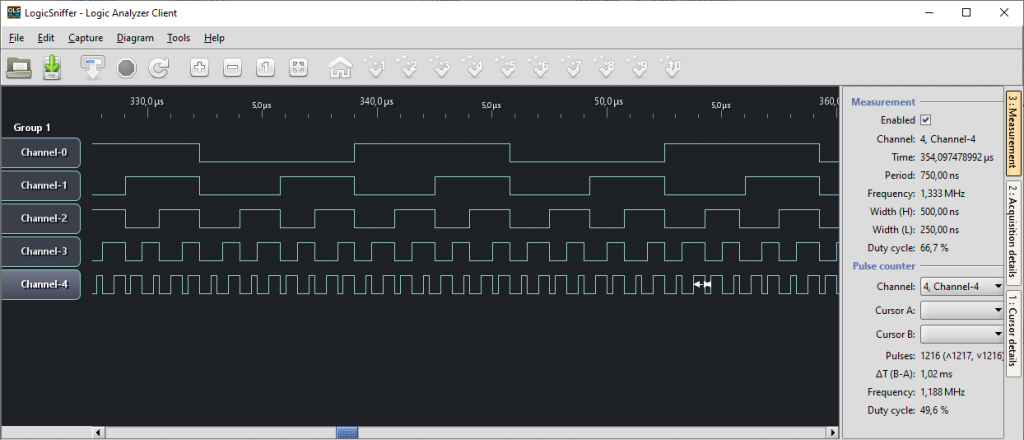
You can clearly see that the frequency is doubled in each channel, starting with the lowest in channel 0, where they are also verified from the Measurement tab.